Dois Sentidos Dissipação de Calor Pwm Quatro Fios Ventilador Temperatura Controlador Velocidade Display Parar Placa Alarme 12v24v48v
R$ 198,55
DÚVIDAS?
Envie um email para:
Componentes Ativos
Opção de Compra e tempo de entrega
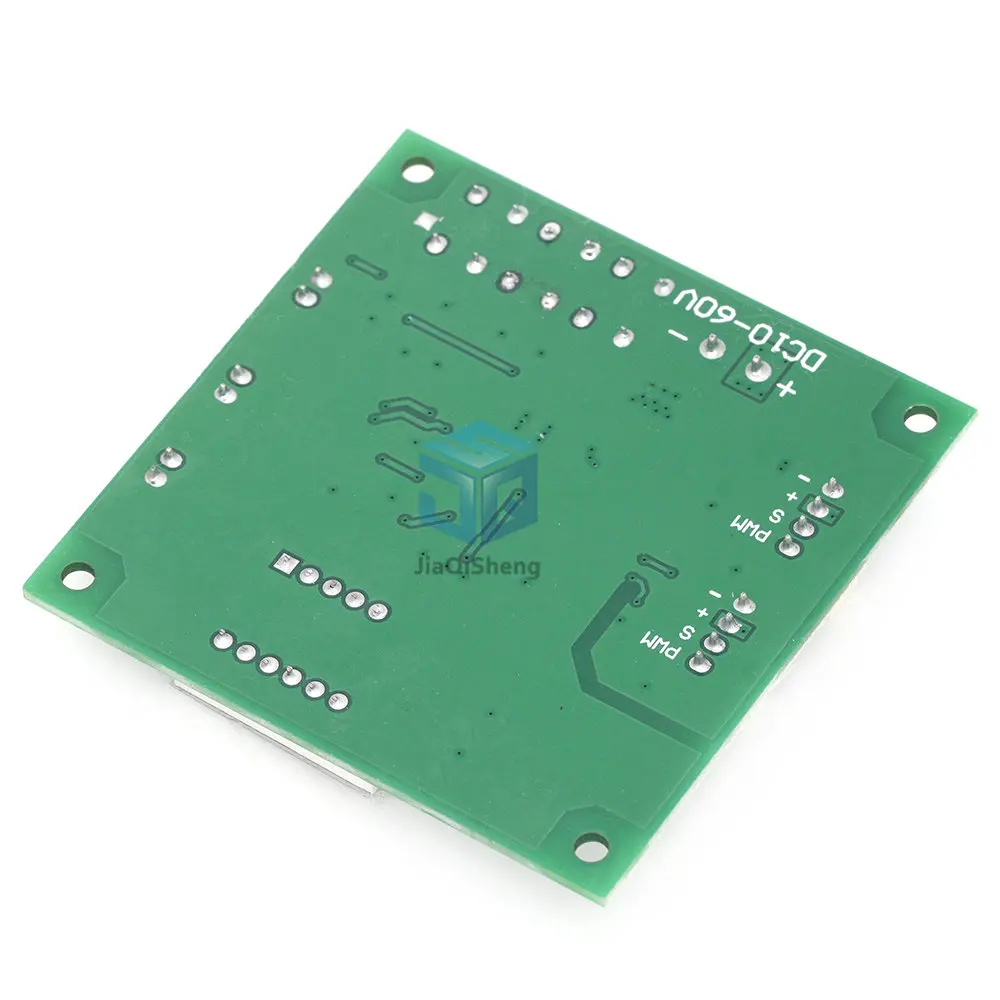
| Veja maiores detalhes nas imagens de referências abaixo |
|---|
Imagem Produto 1 |
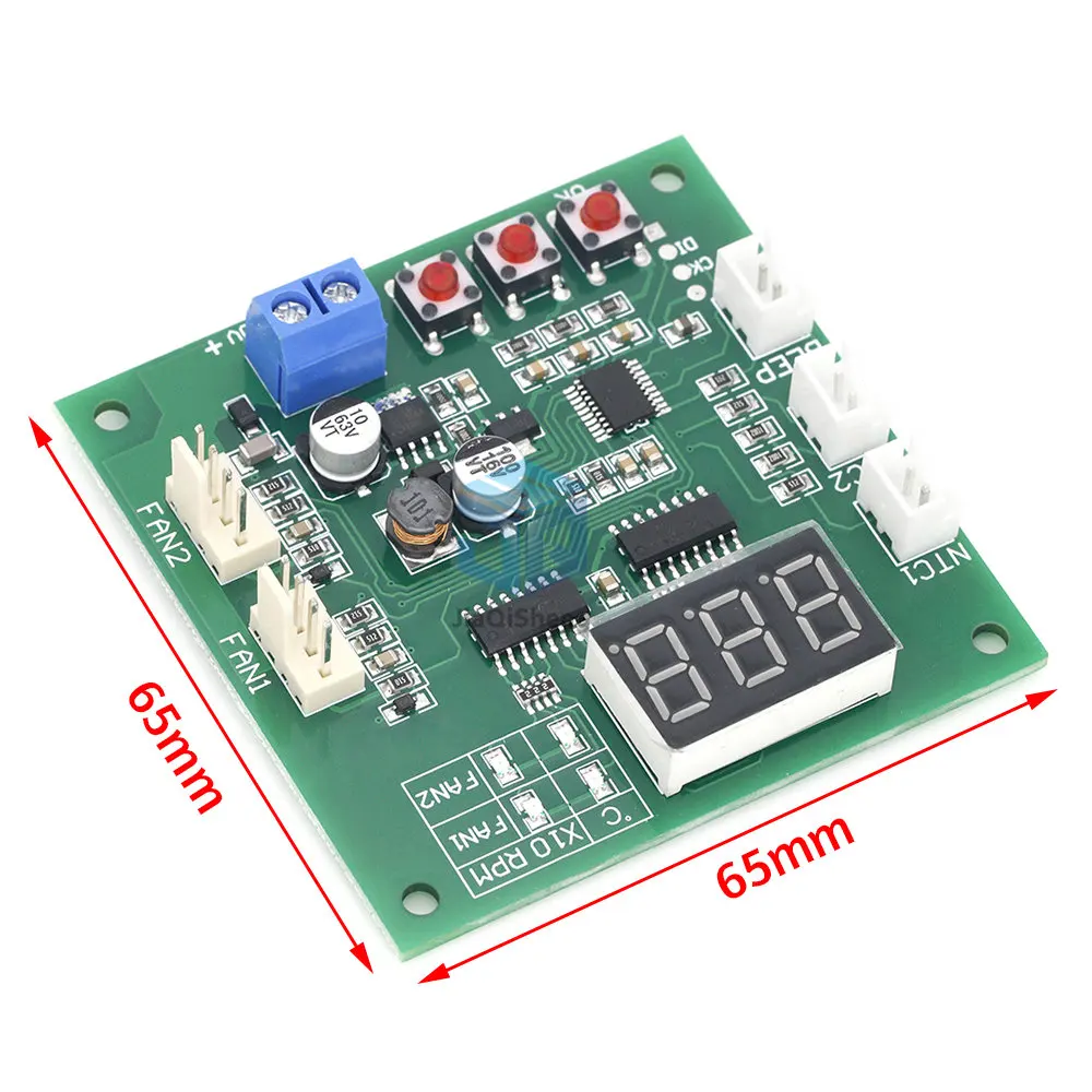 |
Imagem Produto 2 |
 |
Imagem Produto 3 |
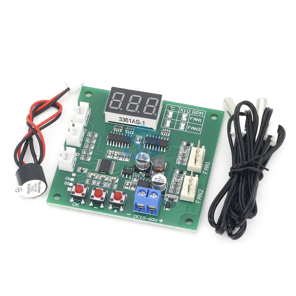 |
Imagem Produto 4 |
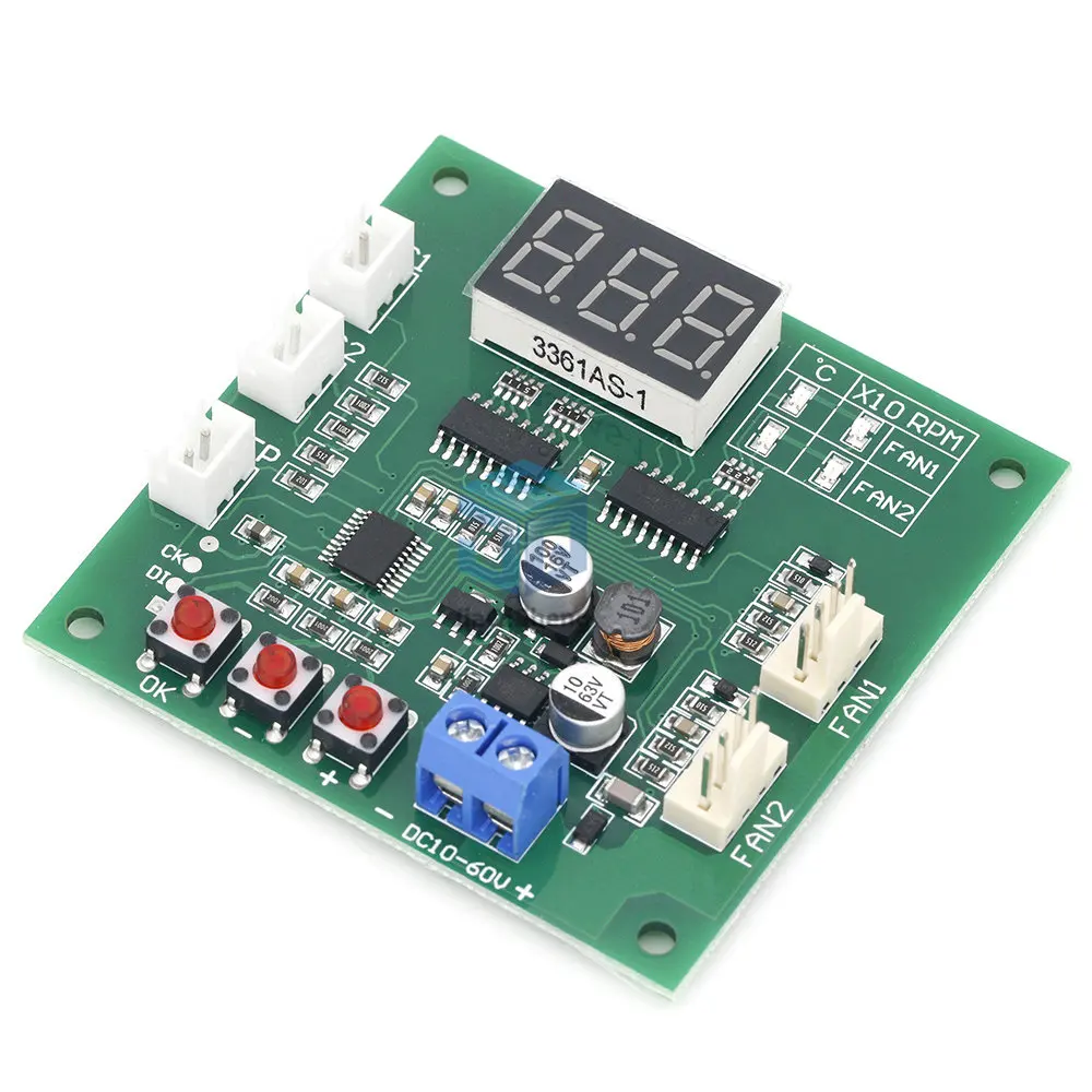 |
Imagem Produto 5 |
 |
Avaliações de Usuários
Seja o primeiro a avaliar “Dois Sentidos Dissipação de Calor Pwm Quatro Fios Ventilador Temperatura Controlador Velocidade Display Parar Placa Alarme 12v24v48v”
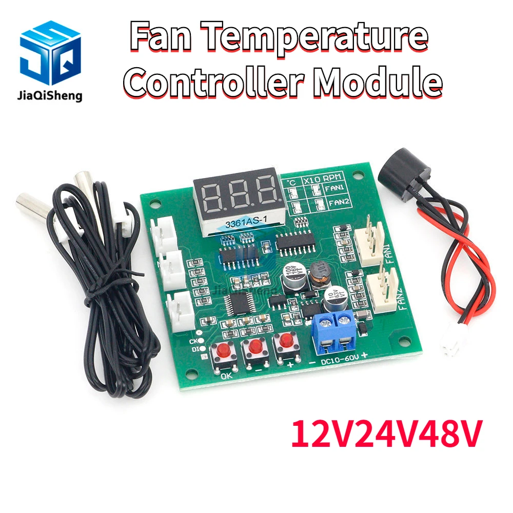
R$ 198,55
Dois Sentidos Dissipação de Calor Pwm Quatro Fios Ventilador Temperatura Controlador Velocidade Display Parar Placa Alarme 12v24v48v
R$ 225,97
DÚVIDAS?
Envie um email para:
Componentes Ativos
Opção de Compra e tempo de entrega
Ficha técnica do produto
| Características | Especificações |
|---|---|
| Número do Modelo | PWM Four Wire FAN Temperature Controller |
| Temperatura de Operação | -40-85 |
| Potência de Dissipação | |
| Tensão de Alimentação | |
| Aplicação | Switch AND Sensor FOR Arduino STM |
| Condição | Novo |
| Tipo | Regulador de Tensão |
| Nome da Marca | Quason |
| Origem | CN (origem) |
Note: This is a four wire PWM fan controller. It can only control fans that meet Intel’s four wire fan specification (most 12-48V four wire fans support it). It can’t control 2-3 wire fans and can’t turn off the fans.
Warning!!!: Although the controller can work between 8-60V, the actual power supply voltage must comply with the fan working voltage. For example, the 12V power supply must be used to control the 12V fan. Selecting the power supply incorrectly may burn the fan and damage the control board at the same time!!
Controller Features:
1. DC8-60V wide working voltage range (this means that the control board can work within this voltage range. In actual work, the controller power supply and the fan are the same, so the power supply must be in accordance with the fan power supply requirements, otherwise the fan will be damaged).
2. dual independent temperature control, display the temperature of the two channels (-9.9? to 70.1?, error <1?) and the fan speed in turn (resolution 10rpm, display up to 999*10rpm, greater than this speed display 999).
3. the low speed of the fan and the temperature control zone are set by pressing the key, with flexible control and large setting range. The program is saved after setting.
4. the stop alarm function of the switch can be set (the external AC buzzer rings for a long time, and it is closed by default).
Performance Parameters:
Working voltage: DC8-60V (it must be equal to the fan voltage. If you use a 12V fan and supply 24V power, the fan will be burned)
Operating current: control board operating current 35mA (12V) 22mA (24V)
Control capability: it is not limited by the fan current, but the pin current of the fan interface on the board should not be greater than 3A current. Please connect the fan power cord directly to the main power supply if you use a fan with a larger current!
Control output range: 10%-100 (this is only the signal output range, and the actual situation depends on the fan performance)
Temperature probe specification: NTC 10K B=3950
Temperature measurement: -9.9? to 99.9?, error 2? (1% probe within 70?) 3? (above 70?)
Temperature control range: acceleration temperature 5-94?, full speed temperature 10-99?
Speed measurement: 10-9990rpm. If the speed is greater than this, 999 will always be displayed. The resolution is 10rpm, and the display unit is *10 RPM (the speed measurement is designed according to the common 2-pole signal fan, and most fans are 2-pole signal)
Stall alarm speed: less than 375rpm
Circuit size: 65mm*65mm*15mm, center distance of locating hole: 56mm*56mm, diameter: 3.2mm
Weight: the total weight of main board + a pair of 1m line cylindrical probes is about 40g, and the weight of individual main board is about 23g.
1. Online Shopping
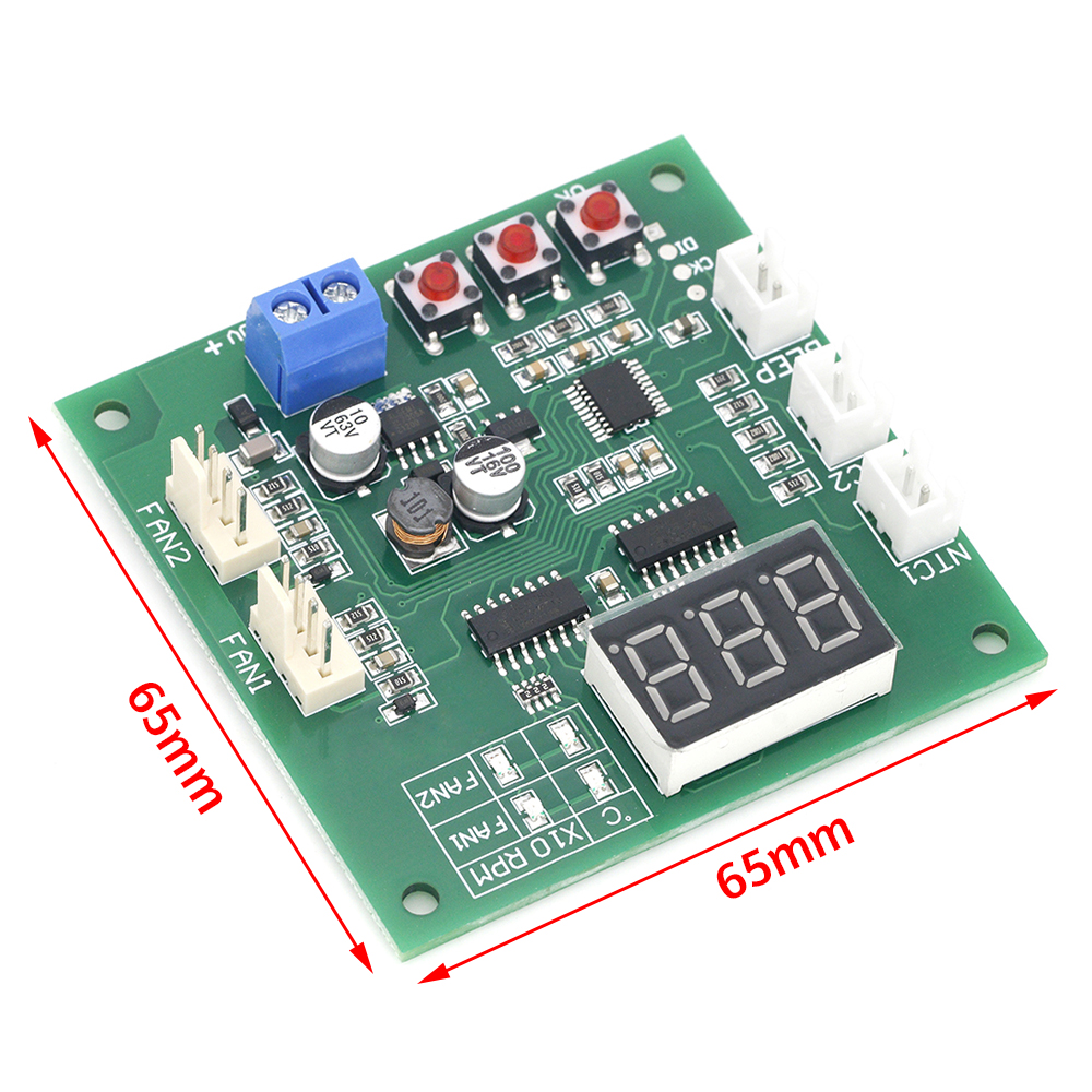
Wiring Instructions:
The blue screw terminal is connected to the main power supply (the power supply voltage is equal to the fan voltage used, and is within the range of 8-60V). Please note that the positive and negative polarity should not be connected incorrectly; The two 4P sockets &channel 1& and &channel 2& are connected to the fan, and the line sequence is negative power supply, positive power supply, speed feedback and PWM control (please refer to the following wiring diagram for details); &Thermosensitive 1& and &thermosensitive 2& are connected to NTC thermistor (parameter 10K B=3950) to measure the temperature with the temperature control of two channel fans respectively; The &buzzer& socket is connected to the AC buzzer. When the stall alarm is turned on, the fan stall buzzer will sound for a long time.
Wiring Notes:
The allowable current of a single fan interface is 3A. If you need to control a fan with a higher current, please connect the fan power cord directly to the main power supply (the control capability of the controller has nothing to do with the fan current, but only the current carrying capacity of the power conductor should be considered).
Display Description:
The control board displays the value through the nixie tube. The four LEDs on the right side of the nixie tube indicate the current value meaning of the nixie tube. One or two LEDs in the row respectively indicate the temperature and speed (x10rpm) of channel 1. The two LEDs in the second row represent the temperature and speed (x10rpm) of channel 2. Under the normal working state, the four values will be displayed in turn according to the sequence. You can quickly switch the values manually by pressing the &+& &-&button at any time. After manual switching, you will stay under this value for a long time before entering the wheel display state. The display of channel 2 can be shielded as required.
Setting Description:
1. basic speed setting: the basic speed setting is used to adjust the fan speed before the temperature control is started, that is, the fan speed when it is lower than the acceleration temperature. The setting method is as follows: press the &OK& key in any running state, then the two horizontal LEDs of channel 1 will be on at the same time, and the nixie tube will display the current setting value (between 10-100). Set the size through the &+& &-&key, and press and hold the key to quickly and continuously modify. After setting, press the &OK& key to enter the basic speed setting of channel 2. After setting in the same way, press the &OK& key again to save and exit.
2. temperature control zone and shutdown alarm setting: under normal operation status, press and hold the &OK& button until l** (** is the value) is displayed, and then release the button. Two LEDs in the horizontal direction of channel 1 are lit at the same time, which means that it is now in the accelerated temperature setting status of channel 1. Press the &+& &-& button to set this value (range: 5-94, unit: Celsius); After setting, press the &OK& button to enter the full speed temperature setting state of channel 1, which is displayed as &H**&, and set the amount in the same way (range 10-99, unit: Celsius); After setting, press the &OK& button to enter the channel I stall alarm setting, press the &+& – &button to set, &boF& means to close the channel stall alarm, &bon& means to open the channel stall alarm; After setting, press the &OK& button to enter the value setting of channel 2. The sequence and setting method are the same as that of channel 1. When the above settings are completed, press the &OK& button to exit and save the parameters.
3. channel 2 display shielding setting: in the power-off state of the control board, press and hold the &OK& key and keep it powered on, and the nixie tube displays &2on& (turn on channel 2 display) or &2oF& (shield channel 2 display), release the &OK& key, set the switch shielding through the &+& &-& key, and press the &OK& key again after setting to exit into the normal working state.
4. switching between normal and anti sequential modes: without connecting the fan, press and hold (Note: hold down) the &+& and &-& buttons to supply power to the controller when the controller is not powered on. At this time, the controller enters the mode selection state, release the button, and click the &+& or &-& button again to switch modes: the display &F-1& is the normal mode, and the display &F-2& is the anti sequential mode, After modification, click &OK& to exit (automatically save when exiting) the setting.
Setting Notes:
1. under the setting state of rotating speed and temperature range, if it does not operate after 15 seconds, it will automatically exit without saving data.
2. when setting the temperature range, the full speed temperature of the same channel must be at least 5? higher than the acceleration temperature. When one temperature value is set so that this condition cannot be met, the controller will automatically adjust another temperature value to ensure that the difference is not less than 5?. This automatic adjustment is one-way. If a callback is required, the other temperature value needs to be manually adjusted.
3. the shielding display setting of channel 2 only affects the data display of the working state, and the control and parameter setting of channel 2 do not affect the normal operation.
Frequently Asked Questions:
1. no display when powered on
The voltage is inappropriate and the power supply is connected reversely —- the controller can operate under the DC8-60V input. Please make sure that the power supply voltage and polarity are correct (note that the power supply voltage should be consistent with the fan voltage).
2. the temperature display always shows -9.9?, the actual temperature is not so low, or the displayed temperature is very different from the actual temperature.
The corresponding channel probe is not connected, the probe is in poor contact or damaged, and the probe parameters are incorrect – check the probe.
3. the fan does not turn
Fan line sequence error – please pay attention to the fan line sequence power line.
Some fans will stop when the PWM value is lower than 20 —- increase the manual speed regulation value.
4. the fan runs at full speed and cannot be controlled. The speed is not displayed
Fan line sequence error (speed measuring line and control line are reversed) — exchange the control line and speed measuring line of the fan (two lines except the power line).
Fan unconventional PWM fan, fake or faulty fan – replace the fan
5. the fan can be controlled normally, but the speed is not displayed
The fan speed measuring line (the third line) is not reliably connected – check the wiring
The fan has no speed measurement signal or the fan speed measurement output port is faulty – replace other fans or ignore the speed display
6. reverse change of fan speed
The fan is an anti time sequence fan. Refer to Article 4 of the setting instructions and modify the operation mode of the controller.
2. 12v24v48v Dois Sentidos Dissipação de Calor Pwm

Avaliações de Usuários
Não existe nenhuma avaliação ainda.
Seja o primeiro a avaliar “Dois Sentidos Dissipação de Calor Pwm Quatro Fios Ventilador Temperatura Controlador Velocidade Display Parar Placa Alarme 12v24v48v”

R$ 225,97


![Novo e Original: 378-470 Mhz 60w 12.5v H2m] 2 Estágio Amplificador 100% Ra60h3847m1 Ra60h3847m1-101 Ra60h3847m1-501 Ra60h3847m1-g501](https://ae01.alicdn.com/kf/Heacd5130f7e94022a9b8dff6140faa33m/100-novo-e-original-ra60h3847m1-ra60h3847m1-101-ra60h3847m1-501-ra60h3847m1-g501-378-470-mhz-60w-12.jpg)




![Blf546 Blf546 [rf Fet 2 nc 9a 65 v 80 w 13db 500 Mhz Sot268a] alta Qualidade Transistor Mos Originais](https://ae01.alicdn.com/kf/HTB1i2uzNgHqK1RjSZFEq6AGMXXaE/blf546-blf546-rf-fet-2-nc-9a-65-v-80-w-13db-500-mhz-sot268a-alta.jpg)


Não existe nenhuma avaliação ainda.